Reverb Karaoke Machine
Mixed-Signal Design
Analog Signal Conditioning
Op-Amps & Active Filters
ADC
DAC
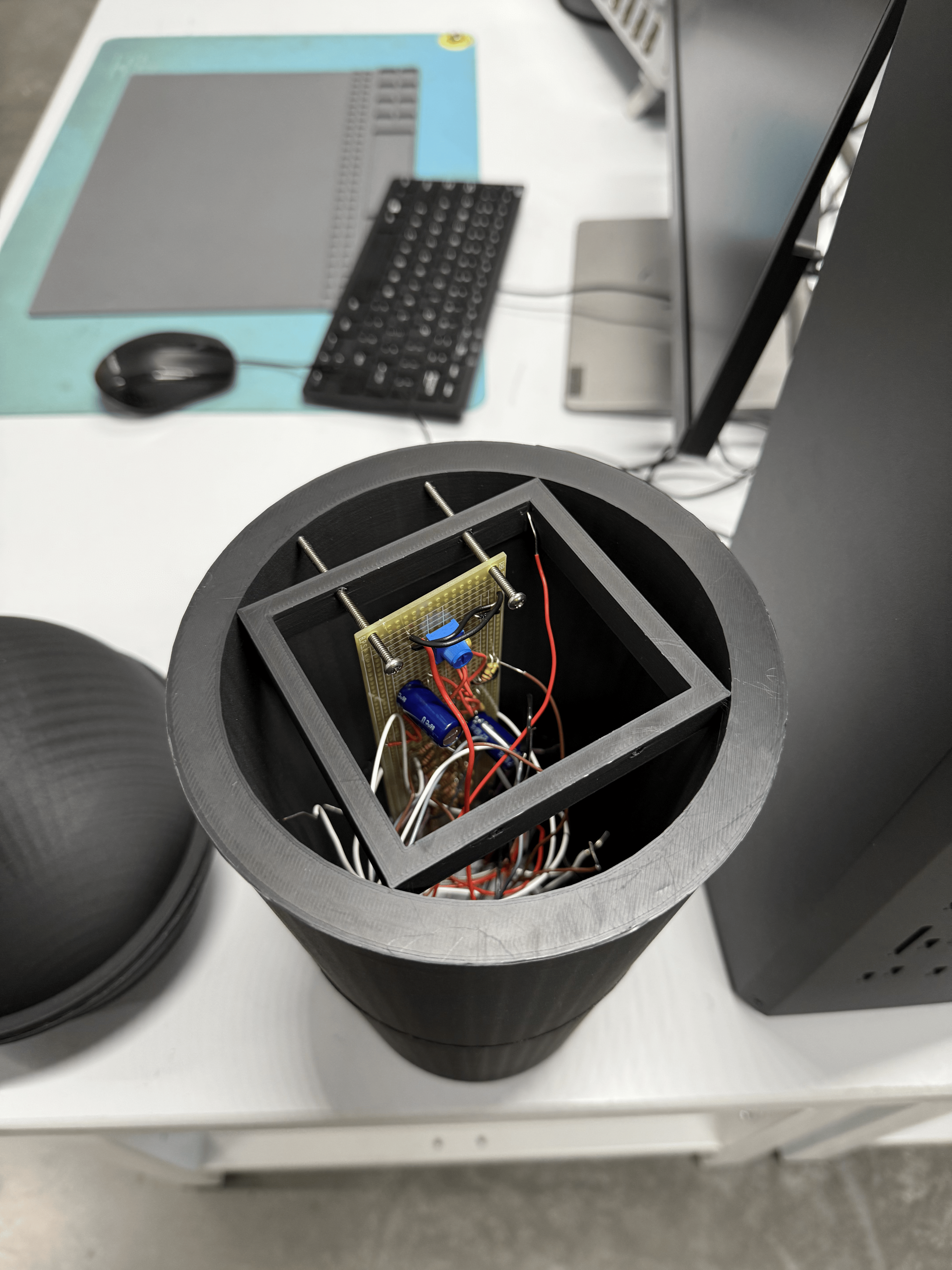
Circuitry inside custom-printed microphone casing.
Built a mixed-signal audio processing system from scratch, handling everything from microphone input conditioning to speaker output.
Analog Front-End:
Designed the input signal chain starting with a low-noise op-amp pre-amp stage to bias and amplify weak electret microphone signals into a single-supply MCU-readable range. Added bandpass filter stage to reject background hum and high-frequency noise while satisfying Nyquist criteria before sampling.
Custom Converters:
Instead of using the MCU's built-in ADC/DAC, I built discrete converters to evaluate their performance. Implemented a 10-bit R-2R resistor ladder DAC and tested a SAR ADC topology. Added output reconstruction filtering after the DAC to smooth quantization steps and eliminate high-frequency images.
Bring-Up & Debugging:
Used an oscilloscope to debug clipping, ground bounce, and other sources of noise across all stages.
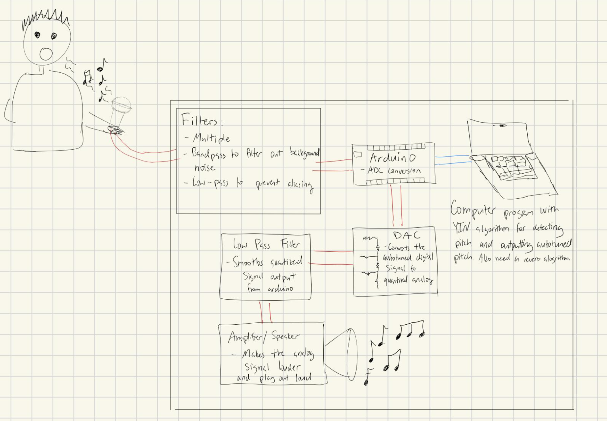
Block diagram of system
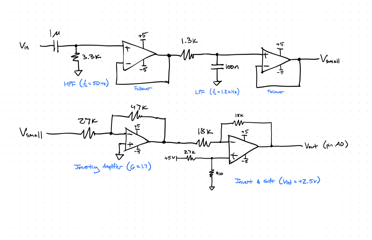
Multi-stage filter schematic
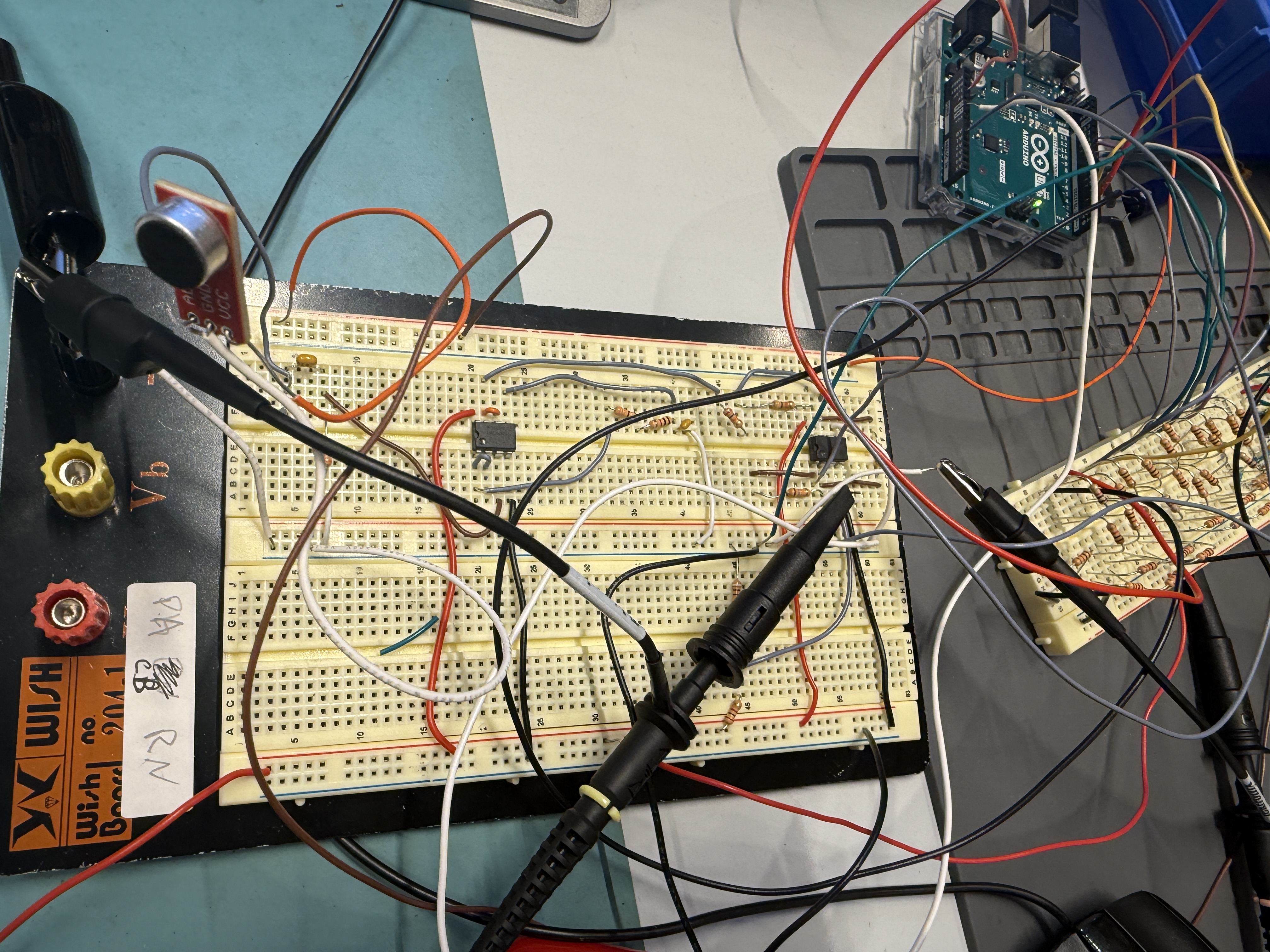
Breadboard bring-up and converter hardware testing.
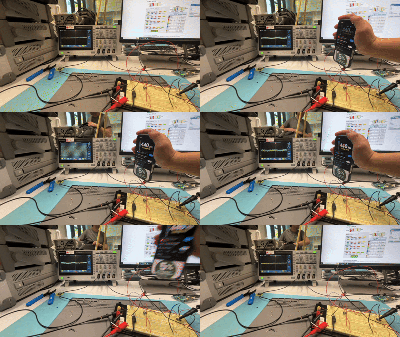
Oscilloscope capture: Raw mic input vs. amplified & filtered output.
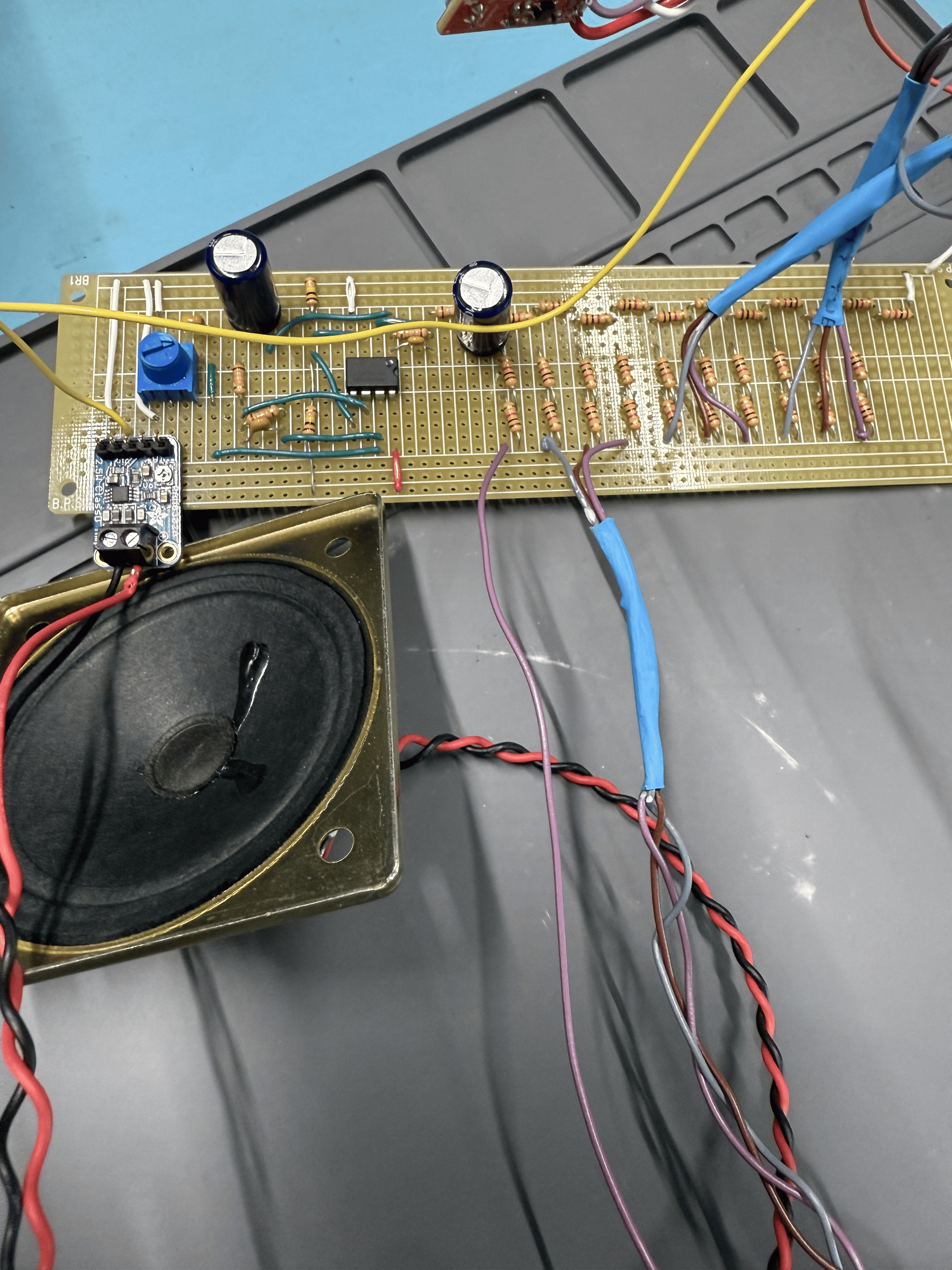
Close-up of the Arduino DAC output.